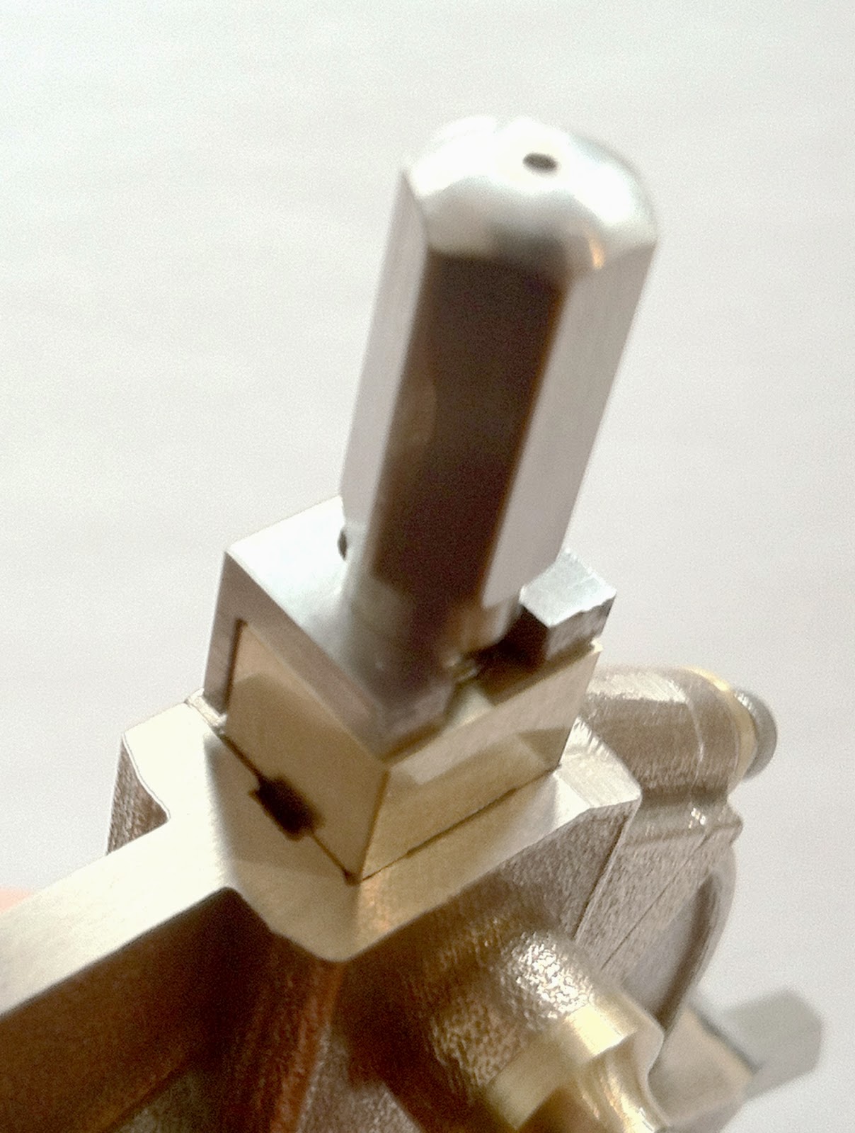
I started with three pieces of 5/16 stainless steel hex rod 2 5/8 long. Since I wanted to turn these between centers to get good concentricity and that means centering and drilling both ends.
To use my steady rest on the hex rods, I needed to make a mild steel carrier sleeve with my lathe that was a light interference fit over the hex rod. This allowed me to use the steady rest (only finger push and mallet tap to adjust right now) to center it all up for center drilling on both ends. This was so satisfying and it worked perfectly!
I wouldn't want to stop here and just go with finger push forever though because I've seen many a steady rest with the brass fingers mushroomed from "tapping" as a way to micro-adjust. It's also just not that accurate as its easy to overshoot your goal causing you to have to reset and start over aligning the part (even more of an issue if you have a sensitive dial gauge in contact with the part while tapping).
 |
| 5/16 stainless Hex rod with round sleeve in slid into place |
 |
| center drilling hex rods (both ends were quick and easy with the steady rest) |
 |
| Hex rods ready to turn between centers |
OK, Here's a sidebar about one of the reasons I wanted the feature of being able to open up the steady rest. When you want to do really accurate centering of long stock, one of the better ways to do it is to use a dial indicator on your tailstock and rotate it around your piece. I made a little offset clamp to hold my indicator and am demonstrating the concept with a piece of round stock in the picture below. You know you are really centered when it goes around with little or no indicator wiggle. This really requires the delicacy of the lead screw advancement to do quickly so I can't wait to have them done. No more "tap, tap" and overshoot.
PS: you can see the neat adjustable drive belt pinch rollers I made to dramatically increase belt traction. Works like a charm. My lathe rarely slips traction now even taking deeper cuts on stainless stock. It had the unexpected benefit of actually reducing the amount of tension I needed thereby reducing wear on the cone bearings in the headstock. More circumferential contact = increased traction. That's another worthwhile project I'll post at another time as there were a couple other upgrades I made that improved traction performance dramatically.
 |
| Using the dial indicator to center stock |
 |
| The offset clamp used to hold dial indicator on tailstock shaft |
 |
| Rotating indicator to set fingers correctly |
I turned the hex rod down to the dimensions of my design for the lead screws (drawings included with the frame parts). It was short work to thread them to 8-32, drill the through hole in the finger clamps and thread those to a matching 8-32 and assemble the fingers for a test fit. I decided to use L-shaped steel garters to hold them in place instead of a c-clip which would have been very, very small and hard to access on this design. Besides, I like the looks of the flush mounted steel-on-brass.
 |
| Turning between centers (on one of my custom faceplates) |
You don't have to turn these parts between centers to get a functioning lead screw but I liked the added assurance of concentricity using this method.
 |
| Dimensioned lead screw from hex rod ready for threading to 8-32 |
 |
| Stainless hex rod becoming lead screw |
 |
| Threaded and completed lead screw |
The hole must be drilled in the finger to allow the screw to pass through unobstructed and align with the finger clamp threaded hole perfectly. I mic'd from the back clamping face to hole center on each clamp separately to allow for any variance and mated each finger to each clamp with the center scribed for drilling. The hole needs to be free fitting but not too big. The step that will be milled into the front face of the finger to allow the garter to fit flush comes close to the hole so do this step with care.
 |
| Finger marked out for drilling |
 |
| Inserting lead screw into clamp and brass finger |
 |
| Perfect fit right to garter shoulder |
 |
| Looks great, just needs the garter |
I fabricated the garters out of mild steel, recessed the front of the finger where they would sit and checked for aligment (Garter drawings included with purchase of frame parts). I drilled, sawed and filed the slots in the tops. Next step, the very exacting drilling and tapping for the 0-80 teensie weensie little screws. bringing out the loupe glasses for this one!
 |
| Garters shaped and scribed for drilling and filing |
 |
| Slot added to garter |
 |
Garter test fit on lead screw shoulder before recessing into finger face
|


No comments:
Post a Comment