Wednesday, April 30, 2014

Step #1: Imagining the WW lathe Steady rest

After weeks of creating temporary solutions for holding longer pieces of stock and after an equal number of weeks searching online for a micro-adjustable steady rest (ebay included), I came to the conclusion that the vast majority of what was available for my beautiful little WW lathe were steady rests with much more basic functionality. Additionally, the vintage steady rests were regularly selling for astronomical numbers on Ebay. I resolved to design exactly what I wanted and make it! (Below is the completed result of what began as this wish to have something better than what was available).
It is now working so well, I decided to do more than post the fun of making it. I'll be offering the main parts as a kit for anyone who is interested and I'll do my best in this blog to detail all the specific process insights I learned while making this wonderful tool .
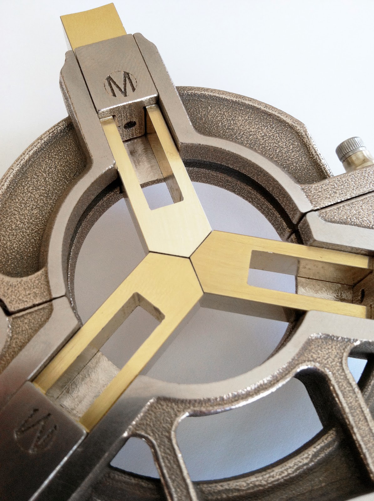
The completed Mowrer WW lathe steady rest
All purchased and fabricated parts for the Mowrer WW lathe steady rest
It is now working so well, I decided to do more than post the fun of making it. I'll be offering the main parts on ebay as a kit for anyone who is interested.
Detailed drawings for fabricating the additional parts are included with the parts you see above.

Step #2: Designing and Modeling the Steady Rest


Preliminary design layout for Mowrer WW Steady Rest
I have a lot of experience in going from concept to prototype as I am inventor with an industrial design degree and am fully trained in drafting and modeling my designs in a 3D program, and have had many of them rapid prototyped using today's cutting edge services available online.
I had also been experimenting with making parts from bronze infused stainless steel from shapeways rapid prototyping service and had been extremely impressed with how detailed, dimensionally accurate and functionally strong the parts made from this material and process were.
Preliminary 3D design

Diving in, I developed a micro-adjuster system that was low profile and could be adjusted with finger pressure yet lock down rock solid once dialed in. I also wanted the steady rest to pivot open like on the big boy lathes for the ability to perform multiple machining operations on a part and replace it into the lathe with extreme accuracy. It's also great for multiple parts in small runs.

It was also important to me to make the design easy to finish. I love doing detail work but I don't love arduous process to get to a beautiful result. I think you'll see more of how I've developed these parts to facilitate easy lapping, filing and minimal machining with maximum accuracy as the steps proceed.

Step #3: Establishing the first surfaces on the Steady Rest frame halves

Well, Christmas in September arrived! The upper and lower parts for the frame were the first to arrive from Shapeways. As you can see, the finish resembles casting even though there is no casting involved. A big difference is that there is no differential cooling shrinkage and warping happening like you get in traditional casting. This means I didn't have to design an overly thick part to remain material safe and that in turn has huge benefits like:
  1. All critical surfaces are very close to final dimensions and can be brought to final dimension with a file and lapping, or you can machine them as well, your choice. I used both.
  2. I am able to include very accurately located guide holes for drilling out screw and pivot locations without having to blue and scribe or spend hours doing centering and numerical set up on a mill.
The raw bronze-infused stainless steel frame parts

Raw lower frame part showing guide holes on the back

Raw upper frame part
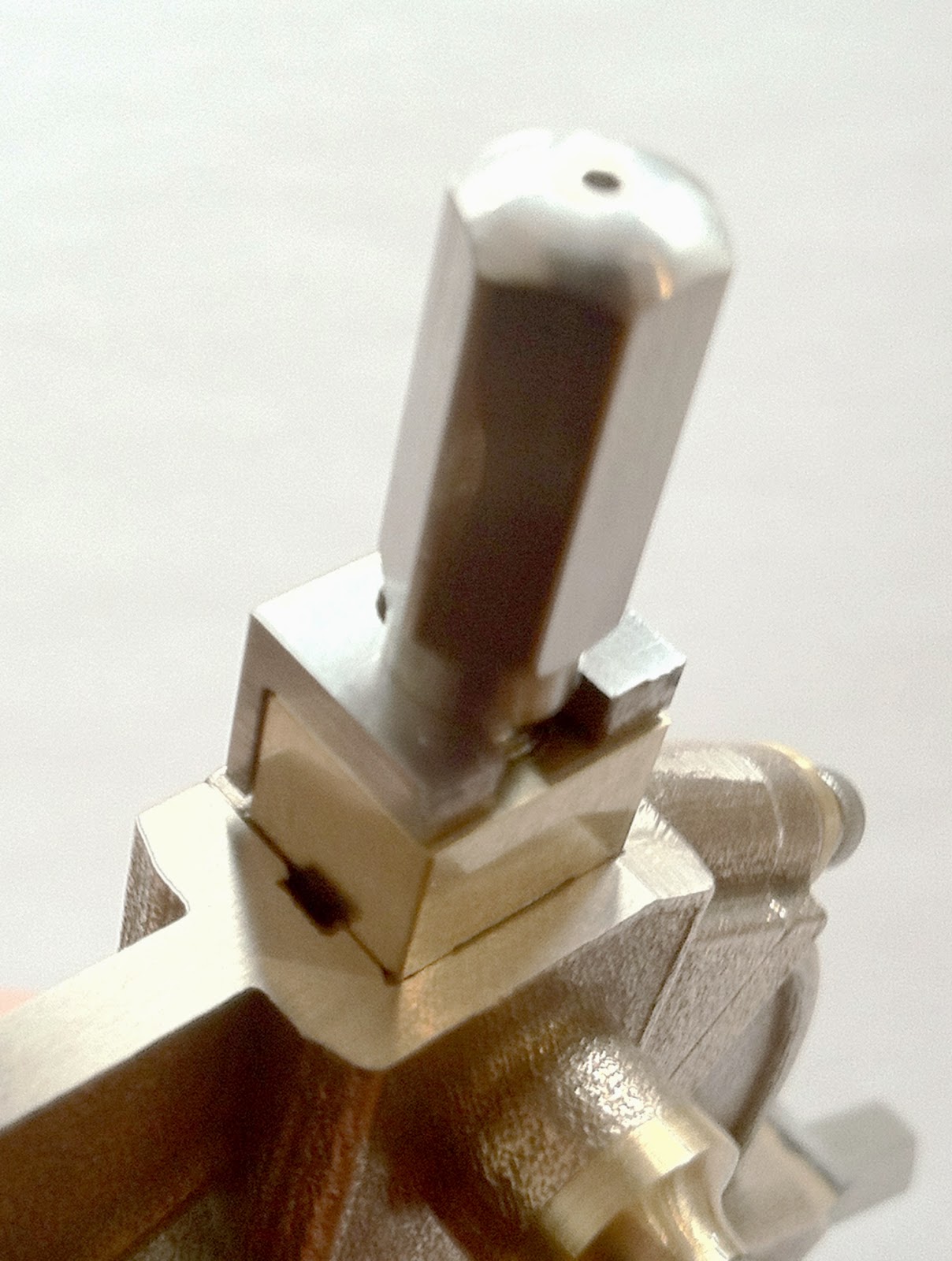
The very first surface to fit are the sides of the two little alignment nibs on the top surface of the lower frame half. This can be done with an edge file (only the edge has teeth), or by milling a very small amount of material off the mating surfaces of the top flat and the sides of the alignment nibs. Be sure to check frequently and take pains to make these surfaces generally perpendicular to the front face of the steady rest (the face without the clamp tightening screws). It's not hyper critical as the true reference surface (the front) will be lapped with both parts held together insuring alignement.
frame mating surface fitting

Step #4: Lapping the front faces on the Steady Rest frame

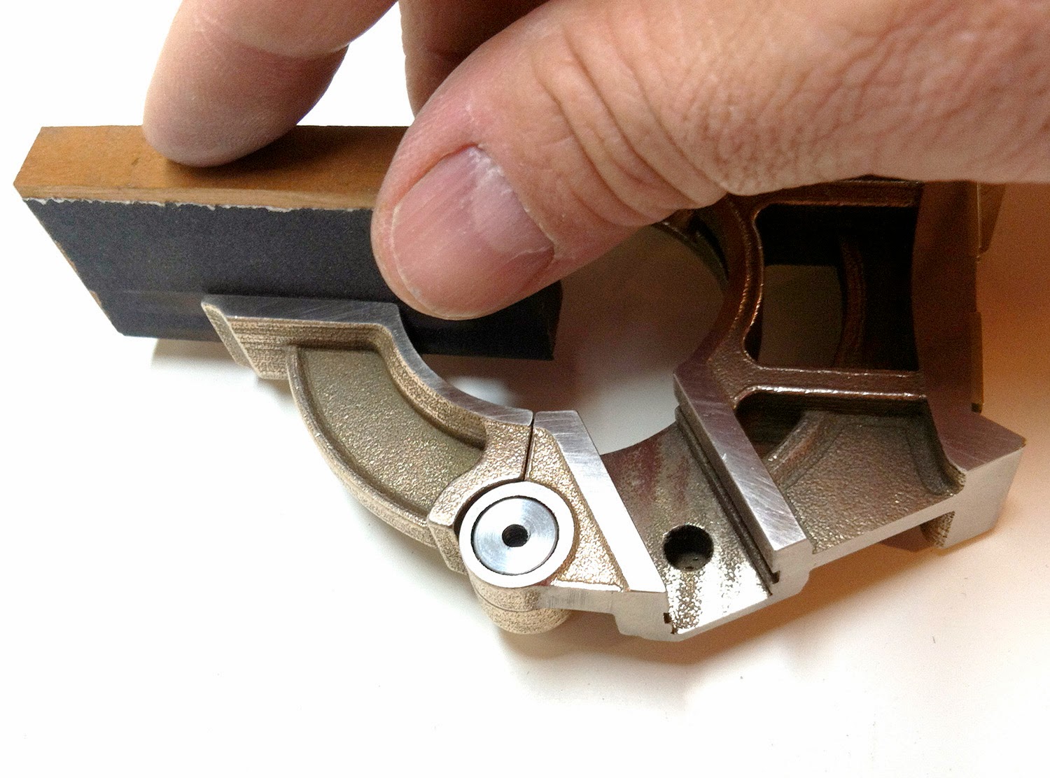
I was careful to keep a slight interference fit on the alignment nibs in their housing slots on the top half of the frame. I can now push them together and easily hold them in place with one hand. This is important because the next step is to lap the "front" face of both parts simultaneously on a flat surface using increasingly finer grits of sandpaper from 80 grit to 600 grit. I designed the frame to work this way on both the front and back. As I lapped, I was careful to keep changing up how I held them and keep doing circles and figure 8's on the abrasive paper so as not to lap more metal off of one side and lose parallel from front to back. This didn't take more than 20 minutes to bring up a great surface that just looks terrific. I stopped at 600 until the whole unit is built because of the scratches I'll undoubtedly get from some of the other work.
Top and Bottom frame parts lapped held together to 600 grit

Step #5: Lapping the back faces on the Steady Rest frame

Rinse and repeat for the back using a feeler gauge to keep testing that you are staying absolutely parallel to the front face. Of course, you can also use a mill to do the same now that you have a good flat front surface to set face down. As with the front, just take off enough to get to a smooth surface. I've designed it so that the front to back thickness is not critical (but parallel is key).

You'll notice I added two brass strips to the saddle surface of the bottom of the frame. You can choose not to but I've just carefully lapped a 15 inch lathe bed that took hours and hours and I want a softer metal touching it wherever I can. There's plenty of material on the raw part to tune the center height to fit any of the WW style lathes.
Back of top and bottom frames lapped

Step #6: Making and installing the pivot on the Steady Rest

With both faces as reference, I machined the mating pivot faces flat. You can use a mill or even your lathe by making a temporary jig to hold it vertical and positioning correctly on your cross slide. With that done, it's a simple matter to clamp the halves together and drill through the guide holes in the parts at the same time. This ensures absolute alignment. The dimensions for the pivot are included in the detailed part drawings included with the kit. You could make the pivot pin out of Air or Oil hardening steel but I found plain old mild steel works fine. Again, your choice. The screw is a stainless steel hex head cap screw 6-32 by .5 inch long. All the finger clamp screws are the same so that one Allen key adjusts everything.
Inserting the steel pivot pin
I've made brass fillet washers for the pivot screw and for all the finger clamp screws as well. I like the addition of the brass with the bronze/stainless color and they spread out the stresses. You can design whatever you'd like here. I chose to make the fillet washer .175 thick for easy finger access to the clamp screw to spin it on and off once its loosened.

View of the pivot pin slightly recessed from back surface with screw and fillet washer
Top securing screw and fillet washer in place

Frame top pivoted open

Step #7: Lapping, back-facing, drilling and tapping the steady rest finger clamps

While I was working on the frame, the finger clamps arrived. They were beautiful and equally as accurate as the frame parts. Little bits of suspension compound remained in the grooves but 2 minutes work with a scribe and they popped right out. Any of the compound that was left deeper in the holes just disintegrate when the drill comes through. It's soft stuff.
I went to work lapping the front faces to great success. So much fun to see things come along so quickly!
Raw finger clamps with suspension compound in grooves

finger clamp clamping screw guide hole
Finger clamp lead screw guide hole
I lapped the face first just removing enough metal to bring up a good shine. Fun to see the "M" monogram on the parts. I then held the clamps in a chuck and centered the guide hole on the rear stem for accuracy of turning and drilling. A four jaw chuck would have worked as well. I then turned the shaft down to .225, a free fit in the cast barrels in the frame. I also faced off the back of each clamp removing about .050 in depth to the front face. You can remove more later if need be and this dimension is not critical as long as the back face doesn't touch the frame when the finger is in place leaving enough room to clamp.
facing off the back of the clamp and turning the shaft to dimension
 With the clamp still centered in the chuck, it's an easy matter to drill out the shaft in preparation for tapping it for a 6-32 thread. I'd recommend making the hole just a tiny bit oversized. Bronze infused Stainless likes to grab drills and heat up fast. It likes to grab finished threads too. When drilling, go slow, drill in very short duration plunges, use lubricant and clear chips often. I can't stress this enough. you'll turn the metal blue before you know it.
Drilling out the finger clamp shaft.
Setting the tailstock depth ring so as not to drill through the face of the clamp

Tapping the finger clamp shaft
I almost forgot to mention that in order to fit the clamps into the frame, you'll need to lap, file or machine a small amount of metal off of the sides of the front face of each clamp. I'd recommend doing this in small increments so as not to make them too loose in their channels. a smooth but close fit here helps the clamps to remain oriented when you are finger tightening the lead screws thereby lessening the chances of binding. I did this to a snug fit at this point since I was going to remove a little material off of the channel walls in a following step. Notice that the clamps should fit proud of the surface at this point. You can always remove more material off the back side later if need be. Conservative and cautious makes for fine fits.

Clamps look amazing slid into place
Good fit in frame with proper gap for brass fingers
It's time to drill out the clearance holes for the 6-32 screws in the extended barrels seen in the back of the frame. Here again, the guide holes make super easy work of this and align perfectly. A few more brass fillet washers and the clamps are installed. These washer stand .215 tall and I simply matched the bottom diameter to the outside dimension of the barrels. I like the look.
Clamps, washers and retaining screws installed

Step #8: Fabricating the fingers for steady rest

I could have rapid prototyped the fingers but it's relatively easy to fabricate them from 3 pieces of 2.25 by .75 square brass bar stock and about ten times less expensive. I started by machining down the width of the bar stock pieces as a touching slip-fit into all three slots. They shouldn't rattle but they should slide easily when it's all done but that means starting just a little snug so your final clean up doesn't leave them too loose. Remember that you'll be removing a bit of material from the sides of the channels as well.

Next step is to reduce them to .375 thick from front to back so that the clamps will have a small amount of travel to clamp the fingers down tight. A few moments at the sander with the miter gauge set correctly and the matching 30 degree angles were on the tips. Leave the blanks long at the top right now as you'll trim them during a later operation.

Time for bluing, marking out of the slots at .25 wide and the correct length (detail drawing included with the kit) and a bit of chain drilling and filing had the slots in no time.
The raw brass bar stock for fingers
Fitting finger's width first, then depth
Scribe finger centers and shape tips

Mark out slot to drill and file (or machine)
Sequence showing chain drilling and filing to square
Having a stable vice makes draw filing flat and square possible 
Lapping to a bright finish through 600 grit after all shaping is complete
Before installing the fingers in the frame, the back and side walls of the finger slots need to be finished. You can use a sanding block and careful checking but if you have a mill you can make quick work of this. Again, remove a very, very small amount here. This part isn't for visuals, it's only for flat so leave some of the raw texture but test for flat and level with each other. You don't want fingers meeting up oddly in the center. This is also when you will tune in your finger fit in the channels.
Sanding block

Carefully flatten finger slots side and backs
Fitting the fingers into the frame and inserting the clamps. Pretty!
Perfect match up of finger tips

Step #9: Making the hold down bolt, nut and washer for steady rest

Here's something exciting. Once you reach this point you are very close to using the steady rest. I actually had to use it to fabricate the lead screws for the fingers. In order to use it I needed to jump over to fabricating the hold down bolt and the nut and washer to clamp it to the lathe bed.

The bolt is nothing more than a .25 diameter piece of stainless steel rod 2.25 inches long and threaded both ends with a 1/4 - 20 thread. The body is tapped correspondingly. Be sure not to drill all the way through the foot and break out the top.

The stainless steel nut is fabricated from a short piece of 7/8 diameter hex rod. This is important because there is not room beneath the bed rail to bring your cross slide in very close if you use a star knob on the steady rest. As you can see from the photo, the hex nut solution gives full clearance and is beefy, easy to manipulate, and you can crank it down with a wrench if you need to. The washer is just simple brass. I went one size number drill larger on the tap hole in the nut to make it really "spin" on fast since it's usually a blind operation being done by feel.

(I haven't included a drawing of the hold down bolt, nut and washer in the fabricated parts drawings in the kit. They are very simple to make and as long as it's long enough to clamp up nothing is terribly critical dimensionally and can be designed however you like).
Hold down bolt installed

fabricated Nut and washer

Spins on nicely
Hex nut leaves room for cross slide to be very close
Getting the center height right for your lathe is very important (though not micro-critically so because the fingers themselves adjust). I'm a stickler for this sort of thing myself so I left extra material on those brass wear strips I installed to be removed carefully at this point now that I can locate the center of the confluence of the fingers and test it using a center collet in the headstock.

There's enough material on the raw lower frame itself for this so you could forego the brass inserts and just machine or file the stainless/bronze part to fit at this point. Keep checking for flat, square and perpendicular as you go especially if you are filing versus using a mill for this operation. You'll have to reduce the angled walls of the foot too but go slowly or you'll get too loose a fit side to side.

For perfect alignment, leave it high and sneak up with a file

Check often for perfect perpendicular

Step #10: fabricating the finger lead screws

I started with three pieces of 5/16 stainless steel hex rod 2 5/8 long. Since I wanted to turn these between centers to get good concentricity and that means centering and drilling both ends.

To use my steady rest on the hex rods, I needed to make a mild steel carrier sleeve with my lathe that was a light interference fit over the hex rod. This allowed me to use the steady rest (only finger push and mallet tap to adjust right now) to center it all up for center drilling on both ends. This was so satisfying and it worked perfectly!

I wouldn't want to stop here and just go with finger push forever though because I've seen many a steady rest with the brass fingers mushroomed from "tapping" as a way to micro-adjust. It's also just not that accurate as its easy to overshoot your goal causing you to have to reset and start over aligning the part (even more of an issue if you have a sensitive dial gauge in contact with the part while tapping).

5/16 stainless Hex rod with round sleeve in slid into place

center drilling hex rods (both ends were quick and easy with the steady rest)

Hex rods ready to turn between centers
OK, Here's a sidebar about one of the reasons I wanted the feature of being able to open up the steady rest. When you want to do really accurate centering of long stock, one of the better ways to do it is to use a dial indicator on your tailstock and rotate it around your piece. I made a little offset clamp to hold my indicator and am demonstrating the concept with a piece of round stock in the picture below. You know you are really centered when it goes around with little or no indicator wiggle. This really requires the delicacy of the lead screw advancement to do quickly so I can't wait to have them done. No more "tap, tap" and overshoot.

PS: you can see the neat adjustable drive belt pinch rollers I made to dramatically increase belt traction. Works like a charm. My lathe rarely slips traction now even taking deeper cuts on stainless stock.  It had the unexpected benefit of actually reducing the amount of tension I needed thereby reducing wear on the cone bearings in the headstock. More circumferential contact = increased traction. That's another worthwhile project I'll post at another time as there were a couple other upgrades I made that improved traction performance dramatically.

Using the dial indicator to center stock
The offset clamp used to hold dial indicator on tailstock shaft

Rotating indicator to set fingers correctly
I turned the hex rod down to the dimensions of my design for the lead screws (drawings included with the frame parts). It was short work to thread them to 8-32, drill the through hole in the finger clamps and thread those to a matching 8-32 and assemble the fingers for a test fit. I decided to use L-shaped steel garters to hold them in place instead of a c-clip which would have been very, very small and hard to access on this design. Besides, I like the looks of the flush mounted steel-on-brass.

Turning between centers (on one of my custom faceplates)
You don't have to turn these parts between centers to get a functioning lead screw but I liked the added assurance of concentricity using this method.
Dimensioned lead screw from hex rod ready for threading to 8-32

Stainless hex rod becoming lead screw

Threaded and completed lead screw
The hole must be drilled in the finger to allow the screw to pass through unobstructed and align with the finger clamp threaded hole perfectly. I mic'd from the back clamping face to hole center on each clamp separately to allow for any variance and mated each finger to each clamp with the center scribed for drilling. The hole needs to be free fitting but not too big. The step that will be milled into the front face of the finger to allow the garter to fit flush comes close to the hole so do this step with care.
Finger marked out for drilling
Inserting lead screw into clamp and brass finger

Perfect fit right to garter shoulder

Looks great, just needs the garter
I fabricated the garters out of mild steel, recessed the front of the finger where they would sit and checked for aligment (Garter drawings included with purchase of frame parts). I drilled, sawed and filed the slots in the tops. Next step, the very exacting drilling and tapping for the 0-80 teensie weensie little screws. bringing out the loupe glasses for this one!
Garters shaped and scribed for drilling and filing

Slot added to garter

Garter test fit on lead screw shoulder before recessing into finger face

Tool Grinding attachment for watchmakers lathe

Hi friends. So I've gotten terribly tired of dull bits and tools. If you're doing any work at all, you end up buying and endless sea...