I've been adding more and more milling capabilities to the beautiful antique 8mm WW lathe I have. With the cross slide mounted vice assembly I built I can move work held in the vice past the cutter in the headstock using the cross slide.
I also want to use the headstock to hold work and machine on the parts using the headstock as a divider. To do so, I needed a way to lock the spindle in place. I've read where some folks use the bearing adjustment nut to clamp down on the spindle and hold it motionless. I don't want to have to keep tightening and loosening this as I move from one operation to the next especially given how critical it is to dial it in well. I've also seen more than a few bent indexing pins that were used to hold the headstock still while machining on the workpiece. Both options are not great.
My solution was to custom design a spindle lock that I could easily and quickly slip onto the headstock and tighten it down to firmly and accurately prevent the headstock from rotating. On most of the other upgrades I've designed, I've tried to remain "non-destructive," meaning I'm trying to alter the antique lathe parts as little as possible, if at all.
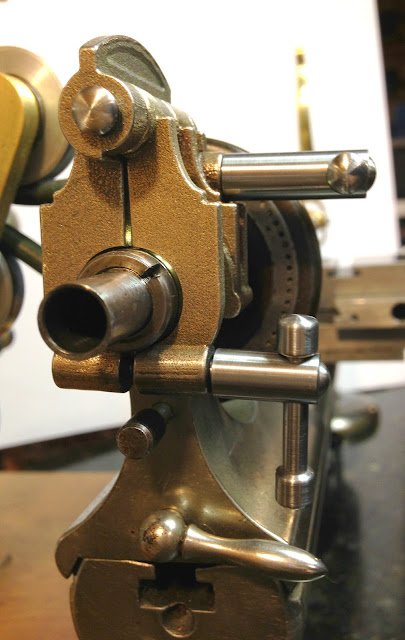
In this case, I was able to come up with a design that is 100% non destructive. Here's an image of it mounted on the lathe headstock. There are 2 pivoting jaws that clamp into place independently on both the headstock frame and on the spindle itself.
I had the design rapid prototyped by Shapeways in their bronze infused stainless steel. I love the performance properties of this material as it is very strong, not brittle and has many of the good wear properties of bronze. It's a little more difficult to drill and tap not because it's harder but because its "grabbier" like bronze. It's nothing that slower speeds and lots of cutting fluid can't solve.
 |
| Watchmakers lathe spindle lock mounted and clamped |
I began by designing the three casting pieces in CAD and modeling them for rapid prototyping through shape ways.
 |
| Spindle lock cad model |
Once the castings arrived, there was only a little machining necessary to get the spindle lock assembled and ready to go. The holes on the main casting needed to be drilled and threaded to 8-32 and matching clearance holes drilled in the two clamping pieces. I drilled out the pivot hole through all three pieces and fabricated a pivot shaft with one end slightly larger for a simple force fit to hold it in place. This way I can remove it for any adjustments I might need in the future.
Additionally, I made the two clamping bolts with sliding levers. I sized them so that they don't interfere with one another during rotation nor do they collide with any part of the headstock. Finally, I adjusted the fit of the inside of the jaws with a bit of careful filing and fine sanding. I've left the casting texture on the parts as I happen to like the juxtapositioning of the industrial look with the finely finished turned parts. Some of you might like to spend the filing and finishing time to achieve a refined finish on the castings or even hit them with a coat of paint to match your WW lathe (some have paint on the non machined surfaces). If anyone is interested in purchasing the castings, just contact me through this blog and we can get you a set.
 |
| Tightening the spindle lock jaws |
And voila! There it is. The spindle lock is rock steady, non-destructive to the antique lathe, and I really like the design of the unit as well. It feels like it belongs on the headstock. It doesn't intrude into the space needed on the spindle shaft for mounting dividing plates or the drive gear for a good threading attachment either (what I'm hoping to get next)...
 |
| Watchmakers lathe spindle lock fully mounted and tightened in place |


Just stunning work!!! Thank you for publishing this!
ReplyDelete