Recently I've been finding myself doing a lot of repetitive cuts on my WW lathe. The constant running of the top slide back and forth, back and forth, for hours, will clearly put a lot of wear on the brass feed nut. I'm also preparing a large project that will require the ability to do some small broaching or linear engraving on parts held in the chuck and that same nut just isn't made for those kinds of pressures. Time to design a solution!
I looked into the various lever actuators that levin and other makers designed and created for driving the cross slide and decided that perhaps these designs could be improved in both function and appearance (Since I love the art of the machine itself, flat stamped linkages don't really appeal to me).
On my little antique derbyshire cross slide, I'm very aware of the limited bearing surface the dovetail ways have so I didn't like the way the commercially available manual levers used a 2 part linkage that for most of its travel, applied tangential pressure on the slide expecting the ways to convert that pressure to linear. Again, I'm always searching for ways to help this little, high accuracy lathe, perform better while reducing the forces and pressures on its various parts.
My solution was to create a linear shaft drive with its own inherent bearings that would handle the tangential forces of the lever and deliver perfectly linear push and pull to the top cross slide.
Here's the results:
 |
| Watchmakers lathe cross slide lever |
I'm very happy with how the tool works, gliding smoothly in and out with only gentle finger pressure while giving me very fine feed control and "feel" for the cut. I'm also pleased with the appearance and how it adds to the victorian quality of the lathe and the parts I've been designing.
I designed the part in a 3D program and, like the other castings I've been using, ordered them from shapeways.com in bronze infused stainless steel. This materials is extremely strong and very wear resistant. I machined all the brass parts from brass round stock and made the custom bolts and screws from stainless hex rod.
 |
| Watchmakers lathe cross slide lever parts |
The lever linkage is designed to be adjustable and there is an additional travel limiting brass collar on the back of the push shaft.
 |
| Lathe cross slide lever forward |
 |
| Lever frame handle withdrawn position |
 |
| Underside of lever frame |
The main frame attaches to the derbyshire top slide male dovetail ways with a rock-solid clamp. Because the Shapeways castings are so close tolerance, I design them so that I only have to remove about 15 thousands. It's just a couple of light passes (or a bit of filing for those who don't have a mill set up).
 |
| lathe cross slide Frame face lapped showing dovetail clamp |
 |
| Removing lead screw from top carriage |
 |
lathe cross slide
| Mounting lever frame to top carriage dovetail rails |
|
 |
| Lathe cross slide lever shaft mount |
 |
| Installing lathe cross slide lever shaft mount |
 |
| Lathe cross slide lever installed |
 |
| Lathe cross slide lever installed |
 |
| Lathe cross slide lever shaft insertion |
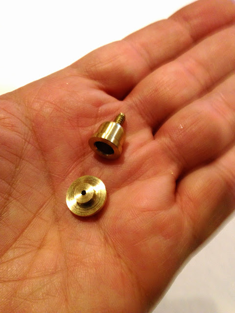
I made the little oiler cups myself and made the tiny caps a very slight friction fit. They don't fall off but pop into my fingers if I give them a pull. I also had fun making the depth adjustment collar in brass. I didn't want it to just be a bit squarish donut. I felt it needed a bit of elegance like the rest of the machine.
 |
| lathe cross slide travel limiting collar |
 |
| lathe cross slide travel limiting collar |
 |
| Lathe cross slide lever oiler cup |
 |
| lathe cross slide liver oiler cup |
 |
| Lathe cross slide lever oiler cup installed and open |


A work of art!
ReplyDelete